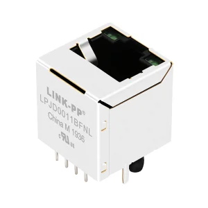
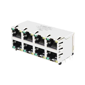
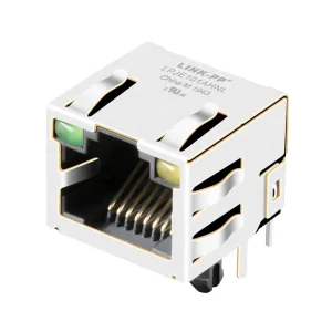
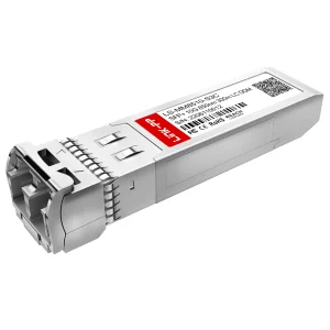
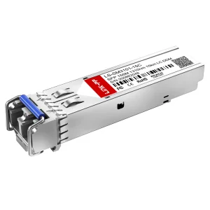
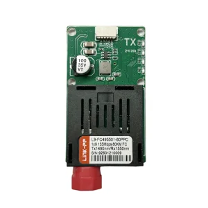
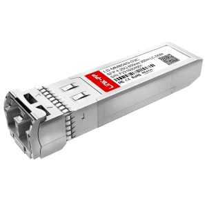
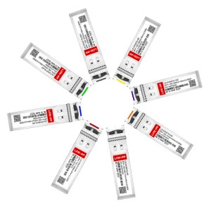
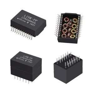
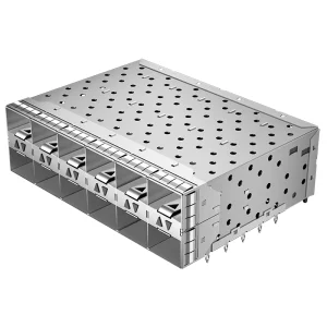
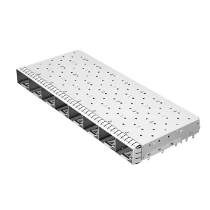
Explore our high-performance RJ45 housings, modular connectors, transceiver cages, and structural solutions designed for enterprise and cloud computing applications.
An Industry Whitepaper on the Evolving Architecture of RJ45 Connector Housing in Modern Edge, Enterprise, and Telecommunications Infrastructures.
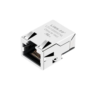
In the current technological paradigm, characterized by cloud-scale infrastructure, high-performance computing (HPC), and dense Industrial Internet of Things (IIoT) deployments, physical interface hardware faces unprecedented challenges. The humble RJ45 Connector Housing serves as a critical structural component, ensuring electrical isolation, electromagnetic interference (EMI) attenuation, mechanical integrity, and environmental survival for high-speed Ethernet communication nodes.
Global procurement teams in telecom, industrial machinery manufacturing, and networking consumer goods face complex choices when navigating the OEM/ODM vendor base. Sourcing is no longer a matter of catalog selecting; it requires finding strategic suppliers capable of delivering highly customized, robust housing solutions that align with exact thermal, mechanical, and signal performance profiles. Understanding the nuances of plastic polymer properties, precision insert molding, and mechanical design limitations is essential to preventing field failures and maintaining system reliability.
Modern telecommunications networks rely on physical hardware that can handle elevated frequencies and power-over-Ethernet (PoE) current levels without thermal degradation. In data centers and switching stations, high-density layouts generate intense heat, making material selection for RJ45 housings critical. Premium OEM/ODM manufacturers utilize Liquid Crystal Polymers (LCP) or high-temperature polyamides (PA46, PA9T) to resist lead-free reflow soldering temperatures while maintaining precise structural tolerances.
Beyond material stability, shielding plays an integral role in data integrity. Grounding tabs, multi-point contact panels, and integrated EMI fingers are incorporated into shielded housings to establish a 360-degree conductive path. This attenuates external electromagnetic noise and limits cross-talk between closely packed multiport designs. By using advanced simulations, OEM suppliers can tune the physical dimensions of metal cages and housings to create effective Faraday cages around the internal contacts.
Proven operational metrics reflecting our dedication to engineering precision, strict quality control, and global scale in interconnect components.
A comprehensive matrix detailing mechanical, electrical, and materials-science dimensions for advanced housing implementations.
OEM engineering projects demand clear, data-backed standards to guarantee structural and electrical compatibility with regional telecom networks. Below is a specification comparison table highlighting standard commercial-grade versus high-durability industrial/enterprise-grade RJ45 connector housing systems.
| Physical Property | Standard Commercial Grade | Enterprise / Industrial Grade | Evaluation / Verification Method |
|---|---|---|---|
| Housing Base Polymer | PBT / Nylon 66 | LCP / PA9T / Polycarbonate (PC) | UL 94 Flammability Analysis |
| Shielding Material | Brass, Tin-plated | Phosphor Bronze, Nickel/Gold-plated | ASTM Salt Spray (48h - 96h) |
| Operating Temperature Range | -20°C to +75°C | -40°C to +105°C (Extended to 125°C) | Thermal Aging Chamber Testing |
| PoE Support Compatibility | Standard PoE (IEEE 802.3af) | PoE++ (IEEE 802.3bt Type 4, 90W) | Contact Resistance / Delta T Tests |
| Mechanical Latching Lifecycles | > 750 mating cycles | > 2,500 mating cycles (Engineered latch) | Automation Reliability Testing |
As transmission standards shift from 10G to 40G and beyond (specifically for copper-based local area connections such as Cat8), the design of RJ45 housings is changing. Single-port and multi-port ganged configurations require tighter internal shielding barriers. Minimizing crosstalk at high frequencies requires integrating ground springs directly into the housing's footprint, routing return currents with minimal impedance. OEM and ODM partners are focusing heavily on simulation-driven design, utilizing finite element analysis (FEA) and electromagnetic field solvers to model parasitic capacitance and inductance long before cutting steel molds.
We combine electrical design, structural molding expertise, and scalable production to support global supply chains.
Backed by 128 skilled engineers, we specialize in high-speed optical design, signal integrity, and custom housing configurations. We offer bespoke solutions for wavelength tuning, specific form factors, customized distance specs, and protocol-specific firmware matching.
Our quality verification processes conform to ISO 9001 standards. We utilize automated optical testing, eye diagram analysis, thermal aging, and 100% final performance verification overseen by a dedicated team of 42 QC professionals.
Operating a robust global business model with six years of direct export experience, Transolix maintains strategic partnerships with over 860 certified upstream suppliers. This ensures steady raw-material availability and reliable lead times for high-volume orders.
Industry-standard technical queries resolved by our senior application engineering division.
High-density components generate thermal stress during operation. Engineering plastics like LCP (Liquid Crystal Polymer) and PA9T offer high mechanical stability, minimal moisture absorption, and thermal resistance up to 260°C. This prevents dimensional warping during automated reflow soldering, maintaining precise terminal positioning and physical latch alignment.
At high speeds (such as 10Gbps and above), high-frequency signals are vulnerable to electromagnetic interference (EMI) and near-end crosstalk (NEXT). Fully enclosed metal housings with nickel- or gold-plated copper shells collect EMI noise and discharge it safely to the chassis ground, preserving signal integrity across long cable runs.
Corrosion prevention is achieved by selecting phosphor bronze base contacts coated with a nickel underplate, followed by gold plating (ranging from gold flash to 50 micro-inches). Additionally, weatherproofing the housing using silicone gaskets and engineering-grade polymers ensures reliable performance in damp or dusty environments.
We leverage automated high-frequency testing equipment, Time Domain Reflectometry (TDR) measurements, and inline AOI (Automated Optical Inspection) systems. This ensures every batch maintains consistent contact resistance and dimensional tolerances, preventing field failure risks.
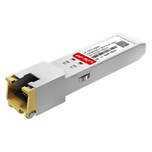
Explore our industrial transceivers, stacked connector systems, and high-frequency communication modules.
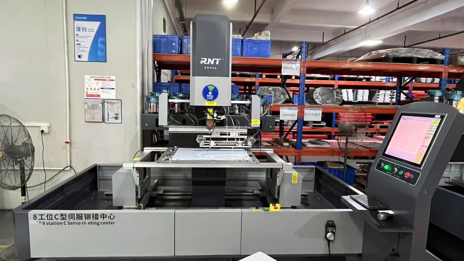
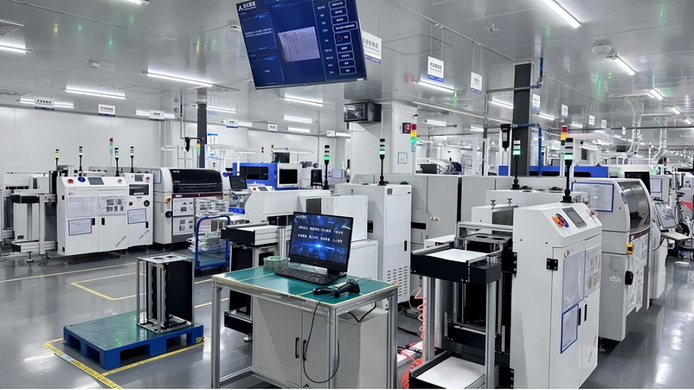
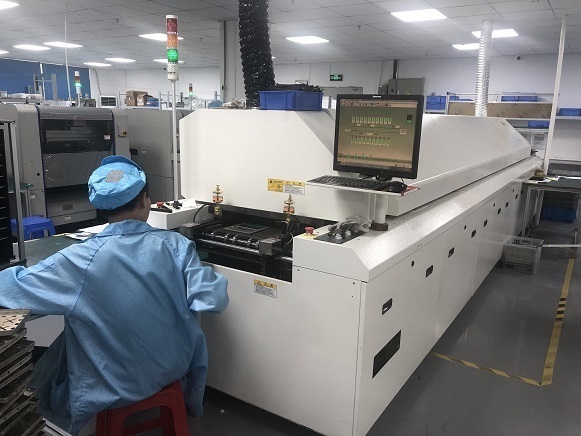
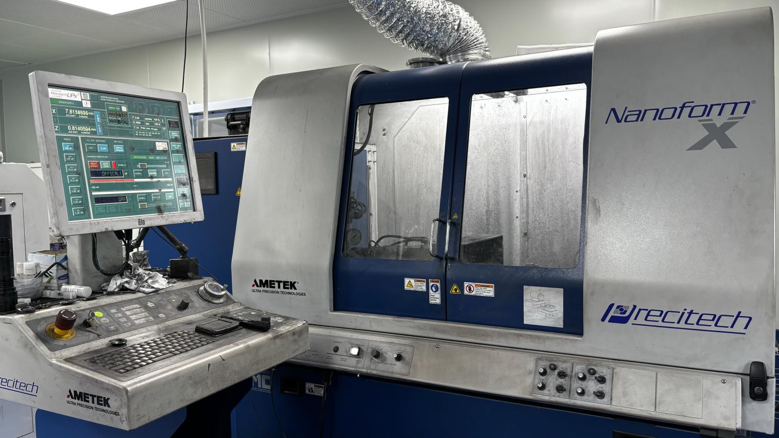
Inside our testing workshops and assembly lines, where high-speed components undergo verification to ensure long-term field reliability.


 Transolix